The Gantry: When Limiting Control Makes a Robot Feel More Responsive
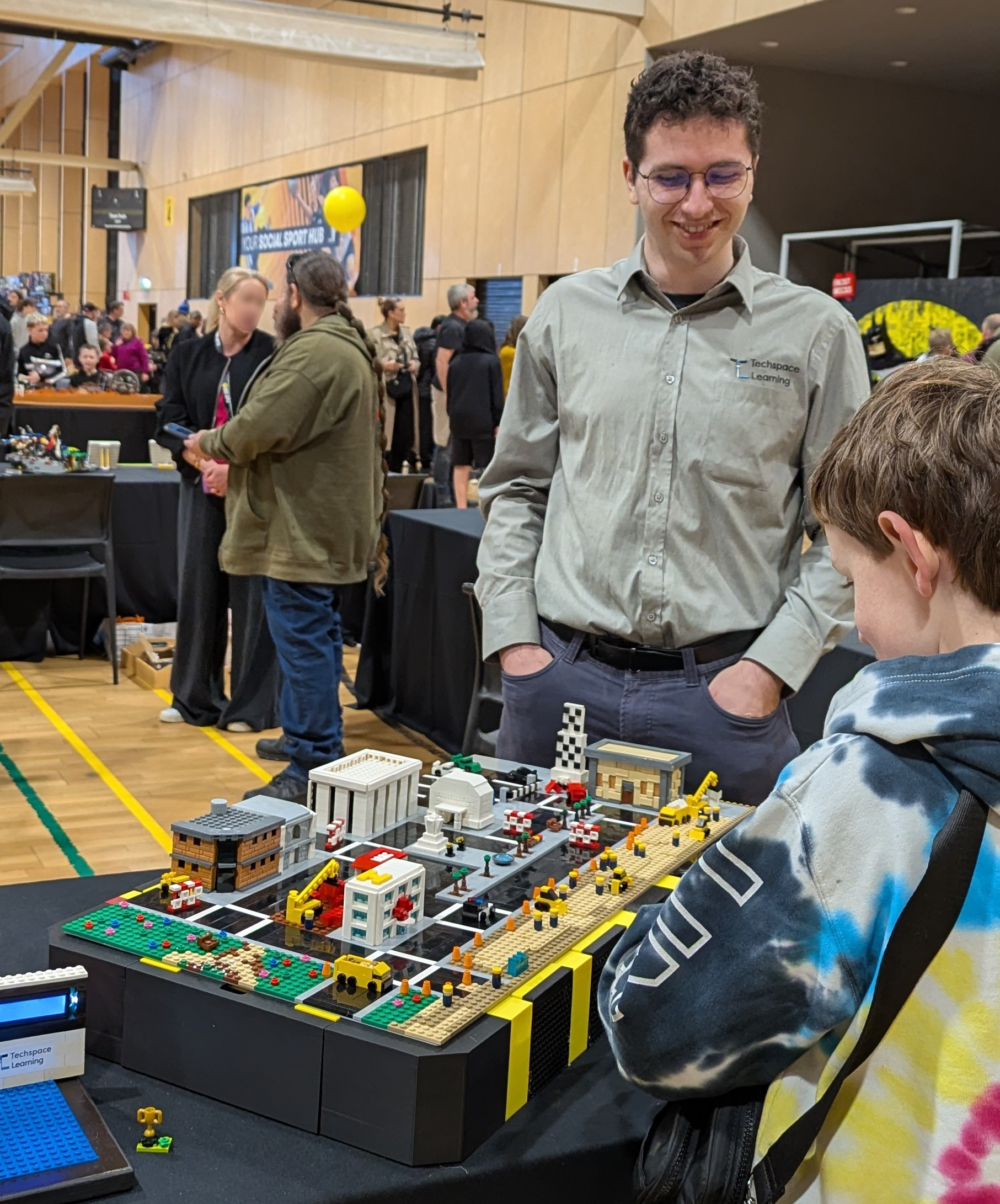
I just finished exhibiting my new robot, the Gantry, at Brixpo, the largest LEGO exhibit in the state. It’s a CoreXY gantry that lets people drive a mini LEGO car around a LEGO city, using a LEGO steering wheel, accelerator, and brake pedal. The Gantry uses hidden magnets, so the cars drive around as if by magic! The crowd ran it non-stop all weekend and everyone loved it. While the robot is simple in theory, I had to come up with some creative solutions - including taking away control from the driver - to make sure it was fun to drive!
I exhibited with Techspace Learning, the STEM not-for-profit I formerly directed. Our displays focus on interactivity - all of our robots are drivable, controllable or respond to people. We know that having interactive robots and being hands on, means we’ll need to do a lot more repairs than if we’d simply said “DO NOT TOUCH.” However, people learn more and have more fun with robots they can touch. As a bonus, it gives us the opportunity to practice fixing things quickly while under pressure as the crowd watches!
This post will highlight what the Gantry does, how it works, and the counterintuitive tricks that made it work.
The Gantry: Overview
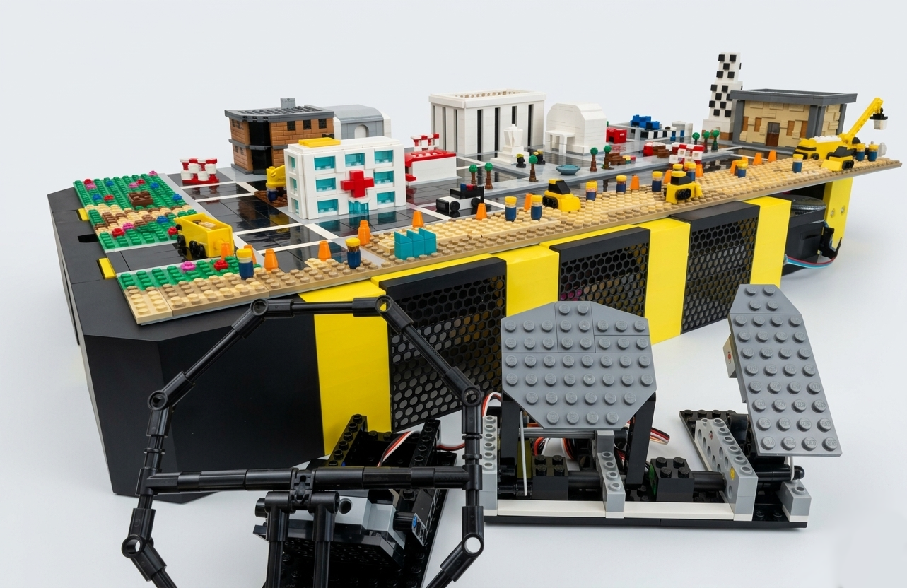
Fundamentally, the Gantry is a CoreXY motion platform using a servo motor and passive magnets to move a LEGO car in a miniature city, letting people drive around.
I wanted to build a CoreXY platform from scratch, and just needed to find a problem to solve with it. I got inspiration from exhibiting at LEGO exhibitions over the past decade, when I exhibited my LEGO coin sorting robot. People would always have model cities and they looked fantastic. While competing with robots in the United States, I visited LEGOLAND San Diego. They had model cities with cars that drove around. The cars looked great, but had visible tracks they drove on like slot cars. I had the idea to make a miniature LEGO car that people could drive around through a city, but it took years for me to figure out how to pull off the effect I wanted.
I realised I could combine the projects - the CoreXY platform would power my cars. I began working on the robot that still goes by its working name: “Gantry.”
How it Works
At a high level, it uses both an Arduino Pro Micro and Raspberry Pi 5. The Pro Micro handles reading user input, calculating how the car should move and then moving it. The Pi is responsible for acting as a bridge between the Pro Micro and Dynamixel digital servo motor that rotates the magnets to let the car turn.
The Tool Head
The Gantry platform has a Dynamixel motor on the toolhead. This allows me to move my magnets on the XY plane, and rotate it around the Z axis.
Originally, I’d hoped to use cheaper LX-16A or ST3215 digital servo motors. However, both had significant problems. The LX-16A has a 240° position control, but it can also be used for continuous rotation, too. I first used dead reckoning to control the motor outside of the 240° rotation. However, it depended too much on user input and how the car was driving. Theoretically, the user could never re-align the car to an angle within the 240° rotation, so error could keep accumulating. After spending a few days writing a custom library in Rust to run the LX-16A on an ESP32, I had to scrap it - my dead reckoning approach was too unreliable, so I knew it was time to pivot.
The ST3215 has 360° positioning, which solves the dead reckoning problem. However, it does not have an extended position control mode. That means if you want to get from 359° to 0°, you must unwind, traveling the long way. This is a problem due to how jarring it is to watch the car unwind. Again, I spent a few days writing a custom library implementing the protocol in Rust, but had to scrap it.
In the end, I went with a Dynamixel XC330-T181-T. It supports 360° with an extended position control mode allowing up to 512 complete rotations, meaning it can position itself from -92,160° to 92,160°. The only downside is that it uses a register-based custom control protocol. I began work on a Rust implementation of the protocol to run on an ESP32, but pivoted to using the Raspberry Pi + Pro Micro due to time constraints.
The CoreXY Implementation
I relied on the CoreXY reference mechanism when designing the Gantry. Because it was designed to be used by the public (including small children), I had to make sure it would be robust and safe. Children love looking with their hands, so I wanted to make sure the robot would survive! I designed finger guards and panels to completely cover the front two-thirds of the robot where the public would be. I also wanted to ensure the robot wouldn’t break itself if someone jammed something smaller like a stick or small LEGO brick through the finger guards. I used strict current limits on my motor drivers and had a large E-stop switch that would cut power to all of my motors. I intentionally made the belt drive loose, so that it’d slip if there was resistance. Like the current limits, this restricts torque to reduce the likelihood of it damaging itself. Additionally, I designed self-forming threads in my 3D prints to hold the pulleys. If there was too much resistance, the pulleys would bend and pull out of the plastic.
The Counter-Intuitive Fixes
I began by looking at how video games design cities for players to drive in. I was essentially building a real-life LEGO GTA city, so I wanted to learn what game developers had already figured out. Intuitively, the faster you go, the more fun it is to drive. However, the first lesson was that moving slower makes the world feel bigger - nothing feels more cramped than a city you drive across in 2 seconds.
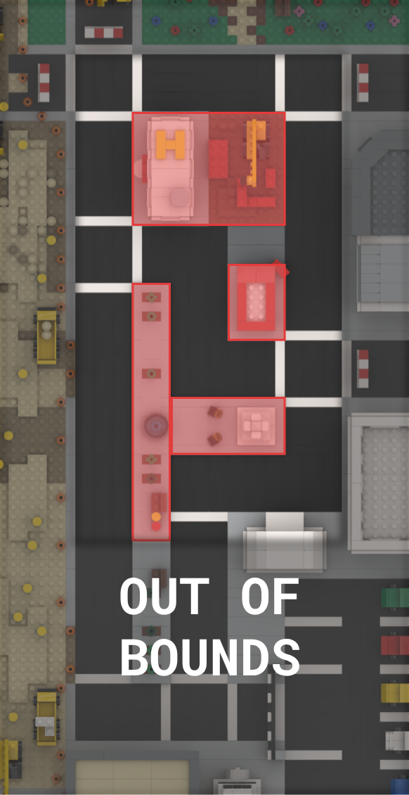
The other issue is control. Originally, I’d coded a simple physics-driven car simulation with basic exclusion zones to prevent the car from driving through buildings. Using the steering wheel, you could drive anywhere. However, the car felt hard to control and unresponsive. You’d often get stuck or cause desyncs, where the car would get dislodged due to getting caught on something but the robot would continue moving. Once a desync happened, you had to manually relocate the car on top of the tool head’s magnet.
The red rectangles are the exclusion zones, the blurred outer area is out of bounds. You could drive anywhere through the rest of the city.
To fix this, again, I looked to level design in video games. I modelled my city as being “on-rails”, meaning you had a set path you were allowed to drive on, and your inputs would only guide you along the path, rather than letting you freely explore.
The blue circles are the nodes (vertices) at intersections, and the lines are the “rails” (edges) you can drive along.
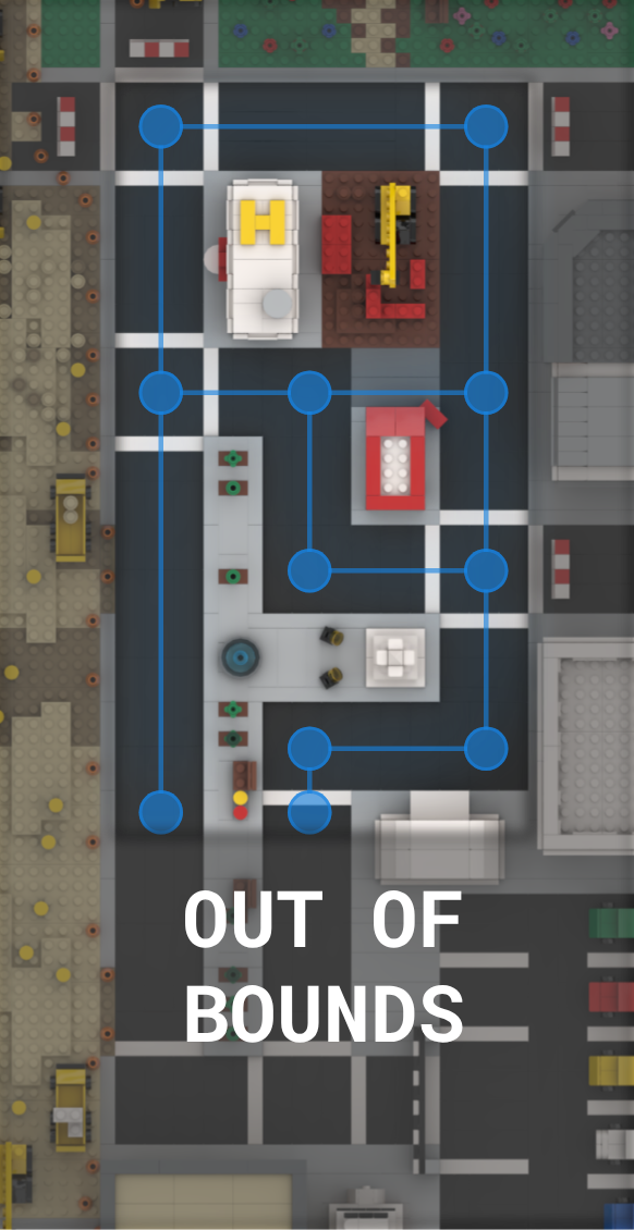
By converting the city into a graph, the driver lost control. Previously, you could turn anywhere, go off-roading, drive on the curb and crash into buildings. However, by limiting you to only being able to turn at intersections, the car felt more controllable. You no longer had to fight the car - the robot guided you along the roads while giving the illusion you have more control than you really do. The main trick in the illusion is letting you move left and right in the lane as you drive straight. This is merely a cosmetic offset, as you physically remain on-rails.
Additionally, at intersections, I estimate which direction the car should go based on the wheel position and available turns. This keeps driving smooth by avoiding the awkward pause when the car needs to wait for a valid direction.
This fix happened at the last minute, and required rewriting my control code days before the exhibit opened, but I’m glad I did. Brixpo was sold-out and the Gantry ran continuously. It was used by easily hundreds if not thousands of people, and not even a dozen noticed something was up with the controls. Everyone else simply appreciated driving around, none the wiser that the robot was only giving them a limited amount of control.
Next Steps
I loved showing the Gantry at Brixpo. It was constantly being used. All the late nights building it after work and crunch to get it done paid off watching people enjoy driving. The highlight was watching parents teaching their young kids how to drive, only in LEGO scale.
Usually after finishing a project, I look forward to starting something new. But after seeing how much everyone loved it at Brixpo, I’m truly excited to improve it as much as I can for our next exhibit!
Immediately, I want to disassemble and inspect the Gantry. I expect some of my bolts will have walked back due to vibrations, and am curious how much the tool head wore down the underside of the city. The tool head keeps a positive pressure on the underside of the city to give the magnets the best possible coupling, but that also means a lot of friction. I expect my pulleys will have naturally bent inwards (as designed as part of the fail-safes) due to the amount of work it did.
Before the next exhibit, I want to redo my electrical systems with 2 custom PCBs. One will handle power distribution, including the E-stop switch, power input, voltage regulators and circuit protection such as TVS diodes, reverse polarity protection and a built-in fuse. Currently, I rely on a mechanical connector to prevent reverse polarity and a fuse in the cable. However, I want to double up, and plan on this becoming a generic power distribution module I can use in all future robots. The other PCB will control the robot, likely featuring an ESP32-S3 to replace both the Pro Micro and Raspberry Pi.
-
Nano Banana 2 was used to remove the background of the image. Everything else in this article was made without AI. ↩︎